On 29 March 2021, the Joint Institute for Nuclear Research received a patent for the mechanical neutron beam filter with time focusing. The authors of the invention, staff members of the Frank Laboratory of Neutron Physics JINR Victor Bodnarchuk and Valentin Sadilov explain the operation principles of the mechanism below.
 At the photo: Victor Bodnarchuk and Valentin Sadilov
The key factor in the quality of obtained experimental data is the signal-to-noise ratio. Therefore, in any experiment, the problem of background suppression is of fundamental importance. In neutron scattering experiments, where the reactor is the source of neutrons, one of the main background suppression tools is a mechanical beam chopper. Its main task is to open a neutron beam-line channel for a strictly defined time interval, which will allow neutrons of the required spectral range as well as neutrons emitted within a certain time interval to pass through. The beam-line channel for all other neutrons should be blocked by the absorbing material of the chopper. This method of forming a neutron beam is used at the instruments of the IBR-2 pulsed reactor. Usually it is a solid cylinder of neutron-absorbing material with a cut-out channel rotating around its axis or a neutron-absorbing disk with a cut-out sector (Fig. 1).
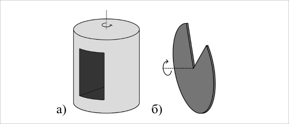 Figure 1. Mechanical beam choppers, which are commonly used in neutron spectrometers. a) drum-type chopper; b) disk chopper
The rotation phase of the chopper is strictly correlated with the pulses of the reactor, and, thus, the characteristics of the neutron beam remain constant for all pulses of the reactor. The neutron spectrum from the moderator at each moment covers the entire energy range, according to the Maxwell distribution. The intensity depends on the value of the reactor power, which in the case of the IBR-2 reactor does not drop to zero even between power pulses. On pulsed neutron sources, the most convenient measurement technique is the time-of-flight method, in which the neutron velocity can be determined from the neutron time of flight from the source to the detector after the pulse. To determine the neutron velocity with good resolution, the number of neutrons emitted beyond the time width of the source pulse should be minimal in the beam, otherwise, these neutrons will mix with the neutrons emitted during the pulse and distort the values of velocities of detected neutrons. The task of the chopper is to absorb neutrons that are emitted between pulses.
The principle of operation of the chopper can be easily illustrated using a time-of-flight diagram, in which time is plotted on the x-axis and the path length is plotted on the y-axis (Fig. 2a). The chopper window allows neutrons with a velocity range from to from the pulse and all neutrons emitted in the time interval Δτ to pass through, while the rest will be absorbed. As we can see from the diagram, the chopper of the type shown in Fig. 1 opens a rather wide time window Δτ, into which neutrons can fly between pulses.
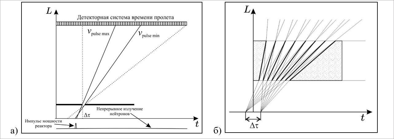 Figure 2. Time-of-flight diagrams of mechanical beam choppers. a) Diagram presenting the principle of operation of a disk (drum) chopper. A detector located at a certain distance from the source counts neutrons in narrow time channels. Each time channel has a range of uncertainties in velocities Δv. The solid lines indicate the spectral range from the pulse itself, and the dashed lines show the whole spectral range of neutrons that are passed by the chopper. b) Diagram presenting the principle of operation of the invention. No neutrons other than those emitted in the time interval Δτ can get into the detector
The proposed invention (Fig. 3) makes it possible to decrease the time window of the source visibility Δτ and thereby remove neutrons emitted between pulses from the beam. This is achieved by the fact that the chopper has a shape of a cylinder and its window is a set of narrow diverging channels without direct visibility, each of which can pass a strictly defined range of neutron velocities only in the required time range (Fig. 2b). The size of this interval and its position on the time axis will be determined by specific characteristics of the design. For the IBR-2 reactor, such an interval should be the reactor pulse. Moreover, the sizes of the channels can be chosen in such a way that the ratio Δv/v is constant for the whole spectral interval.
 Figure 3. Time-focusing mechanical neutron beam filter. The configuration of the channels can be selected in such a way that the neutrons emitted in a certain time interval can pass through the filter channels, and the rest are absorbed
Also, this invention can be used at steady-state neutron sources for the organization of measurements using the time-of-flight technique.